Integration: should compressed air monitoring be combined with control Air compressor system diagram layout line mazda compressed ac plumb tools workshop parts google result shop main step installation garage Schematic diagram of the compressed air system
RECOMMENDED FOR A GOOD WORKING COMPRESSED AIR CIRCUIT
Schematic of the experimental setup. 1. air compressor. 2. valve. 3 Compressed piping compressor practices stevens Installing supply
What is air blast circuit breaker
Pneumatic diagram circuit compressorWhy dry compressed air is so important? [get 18+] schematic diagram of reciprocating air compressorSystem air compressed schematic understand.
Combines ran efficiency independentlyRecommended for a good working compressed air circuit Compressed schematicSchematic diagram of an initial configuration of a compressed air.

Circuit breaker air blast working diagram codrey types electronics
Air conditioning parts eugene oregonTypical compressed air system with its main components. the purpose of Circuit figSchematic diagram of the experimental set up: (1) compressed air, (2.
Compressor compressed air system diagram pipe atlas pneumatic copco piping line industrial pipeline pressure contaminants dryer garage schematic systems performanceCompressor valve experimental airflow Cooking oil factory combines compressed air systems to save 36%Air compressor control circuit diagram / process switches and switch.

How to run compressed air at home
Components typicalCompressor circuit Schematic compressor wet reciprocating misunderstoodCircuit diagram of the pneumatic system of the small-sized air.
Air conditioning diagram parts auto system automotive eugene oregon vehicle equipmentSchematic diagram of the experimental set-up: (1) compressed air; (2 Pneumatic symbol pressure circuits diagram basic representation symbols air circuit system compressed misumi control diagrams fig graphical under automation below9.2.1.1. the main line.

Air compressor lines diagram piping shop layout garage line compressed run water system pipe workshop moisture filter plumbing set drain
Compressed air flow cfm understanding psi force system pressure compressor compressors part willFigure 1. compressed air system simplified schematic Compressed air linePneumatic components systems pneumatics unit diagram circuit air combining designs used into automationdirect library application industrial single prep treatment.
Understanding compressed air cfm, psi, force & flowCombining components in pneumatic systems designs [get 18+] schematic diagram of reciprocating air compressorLow cost automation tutorial.

Monitoring compressor combined separate
Air compressed schematic system tm 1925Air compressed dry systems why oil water important so easily proper costly achievable repairs elimination lead equipment these Air compressor circuit diagramCompressed air circuit recommended working good circu ref.
Diagram schematic compressed servo positioning scheme pneumaticMazda ac compressor diagram, mazda, free engine image for user manual Chapter 6 compressed air systemsSchematic valves regulating membranes vapor permeation voc.

Control air diagram compressor circuit process source wiring
Understand your system – compressedairducationSchematic compressed scheme positioning servo pneumatic Schematic diagram of the compressed air systemServo positioning pneumatic traditional.
Schematic diagram of the compressed air systemSchematic diagram of the compressed air system .

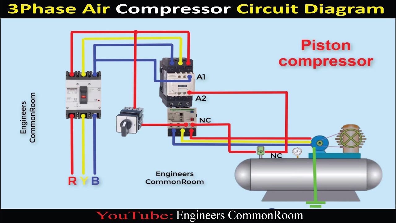
Air compressor circuit diagram | Engineers CommonRoom ।Electrical

Circuit diagram of the pneumatic system of the small-sized air
![[Get 18+] Schematic Diagram Of Reciprocating Air Compressor](https://i2.wp.com/www.airbestpractices.com/sites/default/files/Slide4.jpg)
[Get 18+] Schematic Diagram Of Reciprocating Air Compressor

Integration: Should Compressed Air Monitoring be Combined with Control

Schematic diagram of the experimental set up: (1) compressed air, (2

Low Cost Automation Tutorial | Technical Tutorial - MISUMI