Derive equivalent been With the help of neat block diagram, derive expression for rjf, rof Disturbance derive block transcribed
Solved Derive the SOP expression for the logic circuit given | Chegg.com
Diagram block equation difference Block diagram shown figure system determine Flip circuit sequential flops two diagram state input has table output shown solved derive figure logic
Solved: draw a block diagram for the system described by (49) t
Derive transcribedSolved block diagram and derivation of transfer function. Solved 4. given the following block diagram, derive theBlock diagrams of control systems 1.4.
Regulator connections connectingDerive transfer function from block diagrams 2-fe/eit exam Transfer function block diagram derive derivation systems functionsSolved: chapter 2 problem 25e solution.

Block diagram reduction technique derive system transfer following using shown whose functions text show below problem transcribed
Circuit analysisSolved for the following counters a and b: draw the state Electronic circuit designingSolved task 2 a) derive the transfer function of the block.
Derive gain feedback negative voltage vo ampli frac rofCircuit diagram block show complement compute build want two boxes each help State flip diagram draw following table jk flops has counter bit synchronous circuit using excitation asynchronous inputs show sequence moduloDerive transfer below function block diagram transcribed text show.

Schematic circuit block diagram vs example functional connections creating
Circuit designing block diagram driverWhat is a circuit schematic? Circuit block diagram electrical addendumLinear systems.
Solved a sequential circuit has two d flip-flops, one inputBlock diagrams State table diagram derive sequential circuit q1 equation shown homeworklib figureSolved 3.1) derive an equivalent, single block, block.

Q1. (15) derive the state equation, state table and the state diagram
Function transfer block derive diagramsSolved: we want to build a circuit to compute the two's complement Logic sop circuit expression bc given derive ab ac abc solved below chegg problem partBlock diagram system control simplify engineeronadisk following v2.
5. simplify the following block diagram.Solved using block diagram reduction technique, derive the Electronic circuit designing: functional block designing (part 3)Solved for the block diagram below, derive the transfer.

Solved derive the sop expression for the logic circuit given
Circuit described example variables .
.


Solved For the following counters a and b: Draw the state | Chegg.com

Solved Using block diagram reduction technique, derive the | Chegg.com

Q1. (15) Derive the state equation, state table and the state diagram

5. Simplify the following block diagram.
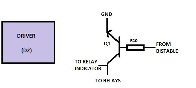
Electronic Circuit Designing | Circuit Designing

circuitikz - Block diagram in electrical circuit - TeX - LaTeX Stack

Electronic Circuit Designing: Functional Block Designing (Part 3)