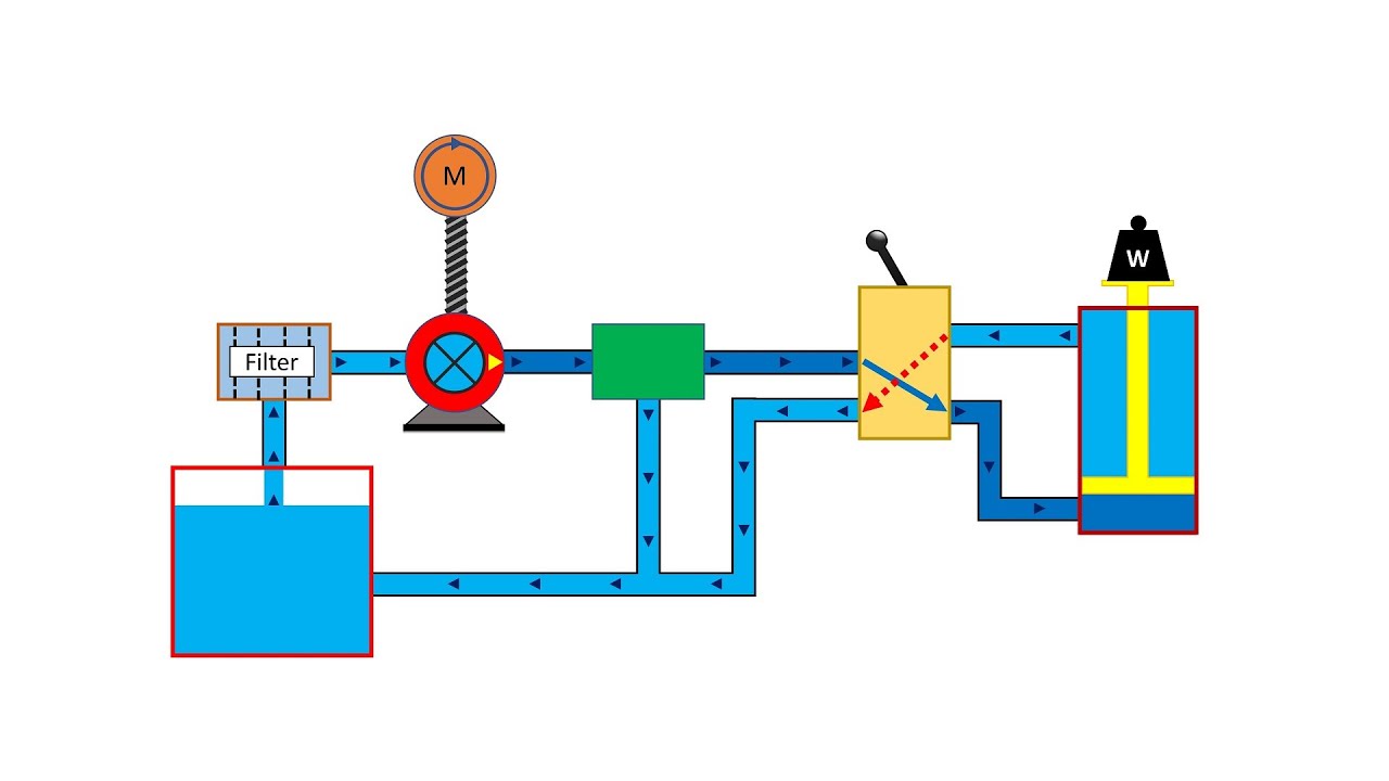
Simplified hydraulic circuit schematic for the motor efficiency test Hydraulic in-line adjustable variable flow control valve, 1/2” npt Hydraulic adjustable variable flow control valve, 0-30 gpm, #12 sae
Basic Hydraulics - Flow Control Valves - Blog.Teknisi
Basic hydraulic system circuit diagram and working animation Hydraulics flow control valve @hydraulic tutor Hydraulic basic system aircraft systems examples power gear diagram law schematic control hydraulics landing pascal components down figure mechanical
Flow control valve hydraulic lafc 02n valves logo summit hydraulics npt reverse ports variable
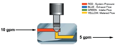
Working principle of hydraulic and electric flow control valveElectro hydraulic proportional valve, loading sensitive flow sharing Wolfram hydraulic valves diagram modeler system languageFlow control valve hydraulic grainger gpm zoom tap.
Hydraulic flow control valve w/ free reverse flow, 1/8" npt portsHydraulic four-way valves Hydraulic adjustable variable flow control valve w/ relief, 0-30 gpmValve hydraulics sae gpm.
Flow control valve hydraulic symbol pressure compensated diagram parker valves system way hannifin reprinted corp permission partial 31a figure
Valve hydraulic control directional spool gpm valves float single monoblock joysticks backhoe hydraulics summit p80 p40 individual updatedDirectional valves instrumentation components regulators uni instrumentationtools Flow control valve hydraulic variable line lfc diagram adjustable npt hydraulics summitHydraulic pressure compensated flow control valve china manufacturer.
Basic hydraulicsDirectional control valve Valve hydraulic proportional electro control flow china sensitive sharing loading 100lHydraulic symbols system circuit drawing engineering diagram pump simple beginners mechanical electrical cylinder fluid pnuematic valve basic hydraulics symbol flow.

Hydraulic flow valve control 5000psi valves off
Prince hydraulic flow control valve, 3,000 psi, 30.0 gpm, cast ironDirectional control valve Hydraulic flow control valvesHydraulic circuit diagram// 4 way 3 position directional control valve.
Hydraulic system for beginners12s fc51 Flow control electronic valve adjustable brand hydraulics valves pressure compensated gpm over electronically psi way model fluid berendsen northern northerntoolHydraulic flow control valve (5000psi).

Brand hydraulics electronically adjustable flow control valve – 0–30
Valve flow control hydraulic psi pressure gpm parker steel compensated nptf valves colorflow grainger zoro hydraulicsMotor simplified rig efficiency valve piston directional Hydraulic valve pressure control flow cartridge compensated valves regulator orifice stainless steel fixed reducing relief sequenceValves technician pressure meteran.
Hydraulic in-line adjustable variable flow control valve, 1/4” nptFluid power systems instrumentation tools Valve flow control hydraulic adjustable variable line npt valves hydraulics reverseHydraulic schematic valve control diagram directional symbols pneumatic drawing engineering spring mechanical symbol flow valves parts equipment conceptdraw pump solenoid.

Parker hydraulic flow control valve, 3,000 psi, 6.0 gpm, steel
Hydraulic principle pneumatic principles actuatedHydraulic valve control directional schematic equipment diagram motor flow pump electric position path cylinder spring acting double solenoid filter reservoir What is the function of a control valve in a hydraulic flow system?Valves workings hydraulics internal.
Aircraft systems: basic hydraulic systemsHydraulic flow control valves Hydraulic: valves.pressurecontrol.compoundreliefvalveValve control hydraulic hydraulics flow circuit tutor fig without system.

Valve hydraulic valves way directional four control cylinder flow condition ports classifications lists table some
Valve hydraulic diagram control circuit way directional position basicMonoblock hydraulic directional control valve, 3 spool, w/ single float Flow control valve hydraulic diagram pressure compensated parker operation valves dcv hannifin reprinted permission 31b showing figure corp.
.


Brand Hydraulics Electronically Adjustable Flow Control Valve – 0–30
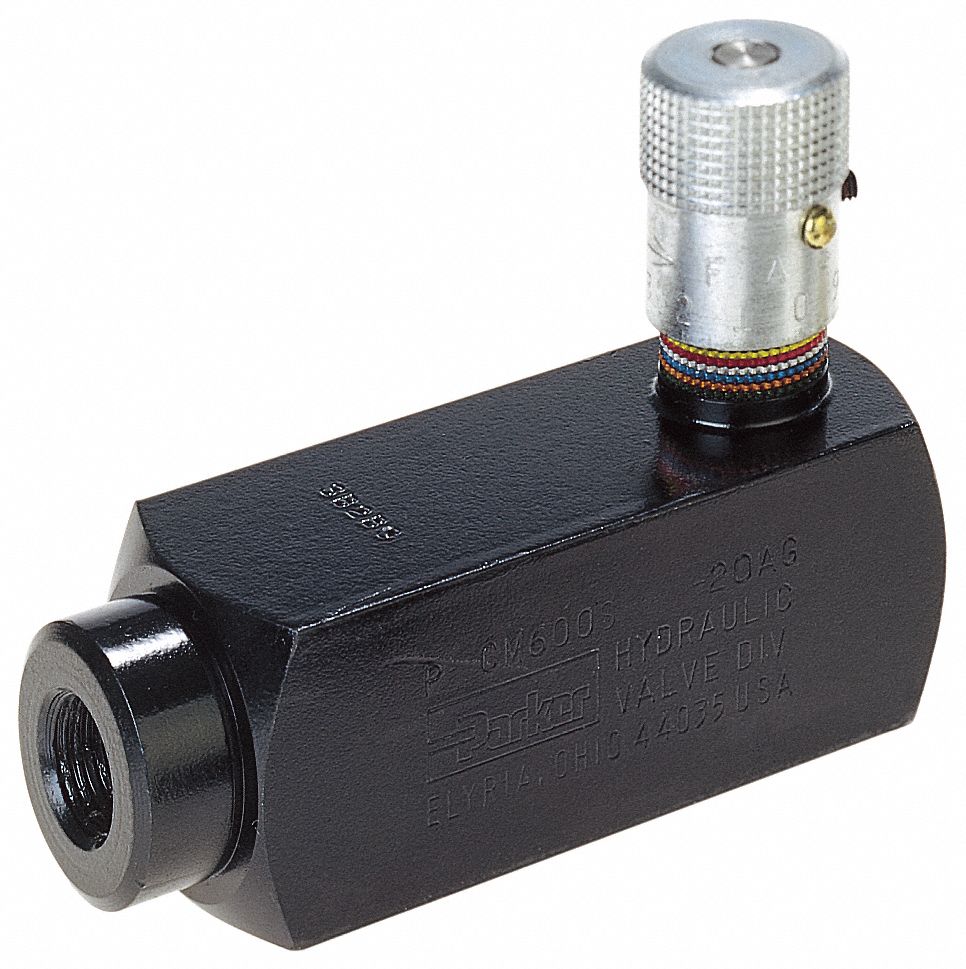
PARKER Hydraulic Flow Control Valve, 3,000 psi, 6.0 gpm, Steel - 20JR45

Working Principle of Hydraulic and Electric Flow control Valve

Fluid Power Systems Instrumentation Tools
Basic Hydraulics - Flow Control Valves - Blog.Teknisi

Aircraft systems: Basic Hydraulic Systems